WB No. 231: Herreshoff Stock Anchors — In WoodenBoat No. 231, Maynard Bray describes the virtues of the three-piece stock anchors first made by the Herreshoff Mfg. Co. over a century ago. For those seeking a deeper understanding of these anchors, we present here Jim Giblin’s original research paper, The Herrehsoff Manufacturing Company Three-Piece Stock Anchor—the work from which Maynard’s article is drawn.
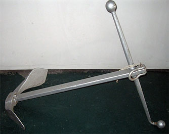
Folding stock anchor.
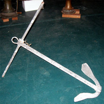
Straight stock anchor.
This endeavor started very innocently as an exercise to satisfy my curiosity and then as often happens spiraled upward.
I have high regard for the Herreshoff three-piece stock anchors and after learning drawings were available at in the Haffenreffer-Herreshoff Collection at the MIT Museum I thought it would be interesting to see what I could discover regarding their design. The resulting investigation has been reveling and I hope this document helps to further illustrate the engineering and design excellence that was the hallmark of the Herreshoff Manufacturing Company. Anchors are certainly an important piece of hardware, none the less; the degree of continued effort that was applied to the design and improvement of these anchors in the search for perfection is terribly impressive and does, I believe, explain why they were so highly regarded by those who used them.
The great number of superb yachts large and small, particularly the magnificent yachts built for the America’s Cup races, tends to eclipse the remarkable, vertically integrated, productive and efficient manufacturing organization that was responsible for their creation. Think about it, two brothers working together in their home town, created and ran a world renowned company whose innovation, productivity, quality, and engineering was unmatched. I have difficulty comprehending the level of intelligence, management skill and self confidence these two brothers brought to this extraordinary enterprise.
The Herreshoff Manufacturing Company: Good management, at all levels, combined with engineering excellence and with intimate knowledge of their work created exceptional products that commanded a good price. What a satisfying place it would have been to work!
J. L. Giblin, January 8, 2013
Herreshoff Manufacturing Company, Bristol, Rhode Island (Courtesy Herreshoff Marine Museum/Americas Cup Hall of Fame).
History of the Herreshoff three-piece stock anchor.
- Charles Frederick Herreshoff, father of Nathanael Herreshoff, conceived the idea of the three-piece stock anchor and had the first such anchor made for him by a local Bristol blacksmith around 1860-70.*
- Another source, Fred Perry- History of the Marine Anchor, states C.F. Herreshoff developed the three-piece anchor in 1873.
- In the 1880s the Herreshoff Manufacturing Company found it necessary to make their own anchors for the yachts they were building.*
- The earliest HMCo. anchor drawing is dated March 29, 1882.
- The last HMCo. anchor drawing located is dated 1927
- Some sizes of Herreshoff designed anchors were manufactured by Merriman Brothers who acquired use of the patterns after the Herreshoff Manufacturing Co. shutdown in 1945. **
* (Common Sense of Yacht Design Vol. 2, pg. 106)
** (Merriman Brothers catalog 1948)
Innovative design elements of the Herreshoff Manufacturing Co. three-piece stock anchors
-
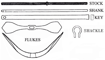
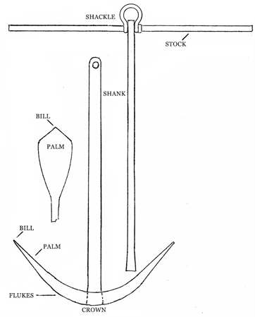
The anchor was composed of three separate pieces, shank, stock and flukes, mechanically assembled with two keys.
- The smoothly curved shape of the palm was a significant improvement over the triangular palm shape of the traditional stock anchor. This innovative feature significantly reduced the potential for the anchor rode to foul the unburied fluke and increased the area of the palm, thereby increasing the holding power of this anchor over that of an equivalent weight stock anchor of the time.
- The edges of the palm were sharp to improve the anchors ability to cut and penetrate the bottom soil.
- A socket connection, at the crown, was used to join the shank and flukes. This eliminated the forge weld commonly used for the purpose and permitted the anchors to be easily disassembled, handled and stowed on or below deck. This also permitted the use of a shank with a narrow rectangular cross section.
- The rectangular cross section of the shank was easily fabricated and presented less resistance to penetration of the bottom soil than an equivalent weight round cross section.
- The rectangular cross section was also stiffer in the critical direction than a round cross section of equivalent weight, any weight saved in the shank could then be placed in the flukes to greater advantage.
- The bill angle of the palm increased as the anchors weight increased, again increasing the palm area
- The design of these anchors was based upon engineering calculations and testing which placed material only where it was required to meet the design loads and improve holding power.
Collectively, these innovations produced an anchor that, in its day had considerably greater holding power per pound than any other.
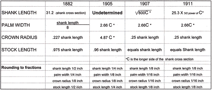
The basic geometric proportions of the HMCo. three-piece anchors remained unchanged throughout the more than 30 year design development of these anchors.
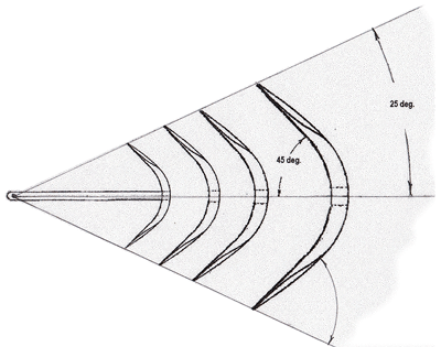
- The flukes at a 45 degree angle to the shank centerline.
- The angle at which the palm initially penetrates the bottom — 70 degrees.
- The angle formed by the shank and a line from the stock to tip of the flukes — 25 degrees.
- The shank was always rectangular in cross section.
- The shank cross section was the design basis for all critical dimensions.
- The straight stock anchor was fitted with a special shackle that served to hold the stock in position when assembled and provided an attachment point for the anchor rode.
The Herreshoff Manufacturing Co. drawings at the Hart Nautical Museum document two distinct styles of the three-piece anchor.
- Three-piece Straight Stock anchors
- Three-piece Folding Stock anchors
In “Common Sense of Yacht Design”, (Vol. II pg. 107) L. Francis Herreshoff speaks highly of an additional style of the larger size anchors which he states were of the same design but fitted with a longer shank and stated his father (NGH) some times called them “sand anchors”.
(The sand anchor is an important matter to document as I have not yet been able to locate any drawings or notes referring to the sand anchor or special, longer shanks.)
The first folding stock anchor drawing is dated 1905. The folding stock anchors were identical to the straight stock anchor except the stock was fabricated in such a manner that it could not be removed from the shank and folded parallel to the shank for stowage. The stock of the folding anchor was nicely tapered and fitted with steel balls at each end. The shanks of the folding stock anchors were slightly longer than a straight stock anchor as they required an additional eye at the top of the shank to provide an attachment point for the anchor rode.
Terms used to describe the Herreshoff straight stock three-piece anchor.
Design development.
The HMCo. anchors were engineered products that were continually refined over a documented span of more than 30 years.
There are four tabular drawings in the MIT Museums Haffenreffer-Herrehoff Collection which document the design development of the entire size range of these anchors except the 7 ½# anchors for the #744 class.
- 1882 Drawing 74-1 describes 21 Straight Stock Anchors from 10# to 640#
- 1905 Drawings 74-44, Straight Stock Anchors & 74-45, Folding Stock Anchors, describe 25 anchors from 11# to 1130#
- 1907 Drawings 74-51, Straight Stock Anchors & 74-52, Folding Stock Anchors, describe 28 anchors from 9.6# to 1250#
- 1911 Drawings 74-54, Straight Stock Anchors & 74-55, Folding Stock Anchors, describe 27 anchors from 8.6# to 1260#
The principle focus of the continued development of the HMCo. anchor design was the strength and stiffness of the shank. There are several drawings, which post date 1911, and provide detail dimensional information on specific anchors. The anchors on these individual drawings are dimensionally identical to the corresponding anchors on the 1911 tabular drawings.
1882
The 1882 tabular drawing depicts only straight stock anchors. However, pattern numbers for the cast steel balls used on the stocks of folding stock anchors appear on this drawing. These pattern numbers are in a different hand than the original drawing indicating they were likely added at a later date. HMCo. folding stock anchors were therefore manufactured prior to the issue of the separate 1905 tabular drawing describing folding stock anchors. Confirmation of this is provided by the photograph dated March 1890 of the torpedo boat CUSHING with a large HMCo folding stock anchor on her fore deck. (Herreshoff of Bristol, page 45) These forged anchors were all produced by the blacksmith shop of the HMCo.
The 1882 drawing contains penciled revisions (no date) increasing the shank cross sections of the 12 largest anchors thereby increasing the stiffness of those shanks. The 1882 drawing used a single radius to dimension the curvature of the flukes and is the only tabular anchor drawing that dimensions the sharp edges of the palm.
Penciled in on the bottom of this drawing is an NGH formula for sizing anchors based upon a vessels hull and spar dimensions.
1905
The 1905 tabular drawings which supersede the 1882 drawing document major developments in the evolution of the Herreshoff anchor and, as stated above, for the first time a separate tabular drawing was issued fully describing the folding stock anchors. Three anchors were added to the 1905 list increasing the number of anchors available to 25 with a range of 10# to 850#.
The 1905 drawings document the development of two very significant design features of these anchors that would remain unchanged.
- The ratio of the sides of the rectangular cross section of all shanks was standardized at 2:1.
- The straight socket connection previously used to join the shank and flukes was replaced by a tapered socket connection. The tapered connection could be assembled more firmly and was therefore less prone to work and loosen under bending forces than a straight socket.
- The curvature of the flukes (the crown) was more rigorously dimensioned by using a pair of equal radii in place of the previous single radius.
- Important dimensional changes were also made:
- The stiffness of all shanks was increased significantly both by reducing the length of most shanks, particularly those anchors over 200#, as well as increasing the cross section of a smaller number of shanks.
- The diameter of almost all stocks was changed, the stock diameter of most small anchors was reduced slightly and the stock diameter of the largest anchors was increased significantly.
The 1905 drawings established a baseline design for the Herreshoff three-piece anchor that was only slightly refined in the years to come. It was apparently both testing and experience that indicated a need to increase the shanks stiffness. Griswold Herreshoff recalled:
“The first anchors were set on shore at a time of low tide and the rode was attached to a team of oxen. Pa (NGH) watched the tipping of the anchor, its initial digging in, and its setting under strain. He then redesigned the proportions with particular emphasis on the flukes. Then there were further tests to revise or confirm the design. In practice, it was found the large anchors bent while the small ones did not. Consequently the sizes were recalculated increasing the scantlings to the 3/2 power of the size” (shank size), (Courtesy Herreshoff Marine Museum/ Americas Cup Hall of Fame- Chronicle Spring 1985).
(Need to determine dates and number of tests conducted. Griswold seemed to indicate there were several tests.)
1907
In May 1907 two new drawings were issued superseding the 1905 drawings, (3) heavy anchors were added to the list for a total of 28, weights ranged from 9.6#–1250#.
Importantly, these drawings provide definitive evidence of the design/engineering effort devoted to these anchors as the formulas used to determine the proof load of the anchors and for calculating the anchors weight appear at the bottom of the drawing. These drawings also document the arithmetic proportions that determined the size of all critical dimensions of the 1907 anchor design and how they were all a function of the longer dimension of the shank cross section ( C ). There were no conceptual changes on the 1907 drawings but clearly some additional engineering had been applied to the anchors.
- The 1907 the drawings are the first to define a proof test for each anchor.
- Once again, to increase stiffness, the shanks of the medium and large anchors were shortened.
- The length of all straight stocks was made to equal the length of the shank.
Arithmetic proportions described on drawing 74-51 May 8-1907.
| Shank Length- D = sq. root of 800 C | Stock diameter- O = .54C nearly | Width of palm- H = 2.66C |
| Short side of shank cross section- B = ½C | Width at neck- F = .54C nearly | Weight = .34(C squared) x D |
| Depth at neck- G = C | Stock length- P = D | Proof test = 49 x weight |
1911
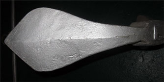
Forged fluke.
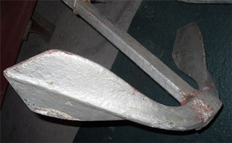
Cast fluke.
In January 1911 two new drawings were issued describing (27) straight and folding stock anchors from 8.6# to 1260#, these would be the last anchor tabulations issued for the HMCo. three-piece anchors. These drawings document two additional important developments:
- A listing of pattern numbers for casting (26) flukes and (12) stocks appear on the January 1911 drawings.
- The transition from wrought iron to cast steel as the material for most flukes and shanks.
The casting pattern numbers were added following the initial issue of the drawing which indicates the castings were phased in over a period of time following 1911. The earliest cast steel HMCo. anchor I can presently document is April 1914. Fluke pattern numbers for the 710#, 805# and 907# anchors were added to the drawing as late as April 1923. It is important to discover exactly when the steel anchor castings were first introduced as there is reason to believe this was another HMCo stock innovation. The stronger cast steel material influenced the following changes to the design of these anchors:
- It permitted the shanks of large anchors to increase in length.
- As dictated by the design geometry the flukes of those anchors with longer shanks also increased in length thereby improving the anchors efficiency. The holding power of these anchors was determined by two principal design elements, the extent of useful holding surface (palm), and the degree of vertical penetration of the bottom soil (fluke length).
- Casting permitted a slightly more sophisticated distribution of material in the flukes and thus enabled the flukes to increase in length without a proportional increase in weight.
The 1911 drawings contain the first reference to galvanizing, however, since these anchors were primarily intended for HMCo. yachts and as galvanizing was a well established industrial process by the late 1870s it is reasonable to expect the HMCo. anchors were galvanized from very the start. The anchor on the deck of the CUSHING referred to earlier certainly appears to be galvanized. Catalogs of the time advertised galvanized anchors. (Providence Tool Company 1879.) On the bottom of the 1911 tabular drawings is an added note detailing the procedure used to establish the assembly fits, of the shank, stock, and flukes, both before and following galvanizing.
The table below illustrates the mathematical relationship of the most important dimensions of the HMCo. three-piece anchors and how they developed throughout the years. All these, except 1907, have been derived from data on the drawings and need to be verified from the NGH design records.
Design development information derived from drawings issued after 1911
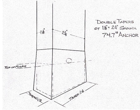
These drawings (1915-1918) all document significant design changes of both the folding stock and straight stock anchors. The folding stock was greatly simplified, the previous elegant tapers have been eliminated, and the folding stock is fitted with a ball on the bent end only. Importantly, these drawings clearly describe, with dimensions, a double tapered socket in the crown of the anchor. The 1911 tabular drawing contains a pencil mark-up also denoting this double taper. All indications are this feature was added following the initial issue of the drawing and thus likely establishes the double taper as a refinement introduced with the introduction of the cast flukes.
Drawing 74-60 March 1915 7 ½ # Cast Manganese Bronze Anchor
This anchor was designed in 1915 for the #744 Class (Herreshoff 12 ½) and therefore was not included on the 1911 tabular anchor drawing. The 1911 design criteria were used to develop this anchor, the geometry is identical but the arithmetic proportions were slightly modified. The 7 ½ # anchors had the same ½ inch by 1 inch shank cross section as the 8.6# anchor design on the 1911 tabular drawing, however, the upper end of the shank was slightly tapered and the palm width was 2.5 inches in width rather than the 2.6 inches that would result if the standard proportion of 2.66C had been applied. The 74-60 drawing depicts the standard HMCo. three-piece construction with pattern numbers for both shank and flukes, casting cards indicate a total of 353 of these three-piece anchors were cast between April 1915 and September 1936. Although the drawing specifies manganese bronze the casting cards indicate that a small number of anchors were cast from other suitable alloys. (Aluminum bronze, Everdur, Navy G bronze)
At the bottom of this drawing, together with an additional pattern number, is a view depicting the anchor with the shank and flukes cast as a single piece thus eliminating the standard HMCo. socket connection. The casting card for this integrated shank and fluke pattern contains a single entry dated June 1, 1939. The order was for a quantity of 50 pieces, for stock, and was filled over a period of eight months. The reverse side of the casting card indicates the pattern was sent to Quincy Adams Yacht Yard in December 1945. (In October 2011 a coffee table created from pattern #12589 and incorporating a 7½# anchor cast from the pattern was auctioned in Hartford Connecticut.)
The 8.6# anchor on the 1911 list of anchors is a bit of a puzzle. It was very likely produced as a wrought iron forging prior to the introduction of the small cast bronze anchors. However, since no patterns were ever made for this anchor it is possible that development of the 7 ½ # anchor for the #744 Class eliminated the need for the 8.6# anchor.
Drawing 74-61 January 29, 1916 127# & 64# Cast Steel Anchors
This is one of a series of individual anchor drawings which identify pattern numbers for cast steel shanks and flukes and provide the detail dimensions required to produce casting patterns. My judgment is the dates of these drawings provide good evidence of the time span during which steel castings replaced wrought iron as the material of construction for these anchors.
This drawing specifies .3-.4 carbon steel (medium carbon steel) as the material for the stocks. The crown socket tapers are fully dimensioned as 1 in 6 on the narrow face and 1 in 12 for the wider face. Casting card No.10779, for the fluke of the 127# anchor on this drawing, is titled “Anchor Fluke for 40 foot Class” (#773-NY 40 Class). The issue date of the drawing was January 29, 1916 and first order for the patterns use was only 16 days later.
Drawing 74-62, March 4 1916 12# and 16# Anchors
The 12 # anchor drawing specifies cast manganese bronze as the material for the flukes and shank and Tobin Bronze rod for the stock. Cast steel is specified for the 16 # anchor. This drawing also fully dimensions the socket tapers in the crown of these smaller anchors as 1 in 8 and 1 in 16. Unlike the larger wrought iron and steel anchors the shanks of all the small manganese bronze anchors had a slight taper to the upper portion of the shank.
The sketch above shows the tapers extending above the top of the fluke casting this increased the shank cross section at the point of maximum stress and appears to be another refinement incorporated with the transition to cast flukes.
Drawing 74-64 May 26, 1917 288# and 199# Cast Steel Anchors
The 288# anchor had crown socket tapers of 1 in 5 and 1 in 10; the socket tapers for the 199# anchor were 1 in 6 and 1 in 12. Thus confirming the shank tapers became steeper as the size of anchor increased. This drawing also provides true fluke dimensions for both anchors and the ability to measure the bill angles of both anchors.
Drawing 74-69, December 18, 1918 & drawings 74-70 (64#&74.7#), 74-72 (545#), 74-81 (470#)
When pattern numbers were added to both the straight stock and folding stock 1911 tabular anchor drawings the same shank pattern number was specified for the equivalent straight stock and folding stock anchors. These four drawings clearly show the cast shank of the folding stock anchor was to now be used for both straight and folding stock anchors versions of these anchors. This made perfect sense as it eliminated the need for the special shackle previously used on straight stock anchors and created a commonality of parts.
Once patterns had been made cast flukes and shanks, particularly the larger sizes, required fewer man hours to produce than the equivalent forging. The steel shanks and flukes were cast both by HMCo. and outsourced from several different foundries. The earliest outsource of anchor castings I can document is February 1915 when 24 flukes for the 127# anchors were ordered from The Malleable Iron and Fittings Company in Branford Connecticut. The transition to castings for anchor flukes and to a somewhat lesser extent shanks may have been driven as much by business considerations as the increased strength of the cast steel material. 1914-1915 was a very busy period for the HMCo., casting the flukes and shanks reduced the demands placed on the blacksmith shop and patterns permitted purchasing uniform pieces from other foundries. Other foundries supplying anchor castings were New England Steel Castings in East Long Meadow Massachusetts, Millbury Steel foundry in Worcester Massachusetts and Lebanon Steel Foundry in Lebanon Pennsylvania. The few surviving anchor casting cards also indicate that by the fall of 1926 Lebanon Steel Foundry was the sole source for purchased anchor castings. The absence of pattern numbers for (15) shanks indicates they would remain forgings. While cast steel was a stronger material and permitted some design improvements the wrought iron was certainly an adequate material that had been used successfully for many years and was not immediately abandoned. Wrought iron is more corrosion resistant than cast steel and when the galvanized coating was damaged or deteriorated as on the sharp edges of the palm the exposed wrought iron would not deteriorate as rapidly as the cast steel. The cast fluke had a more efficient distribution of material than the forged fluke, however an examination of the photographs of the cast and forged anchor flukes indicates it would be easier to clean mud off the smoother forged flukes (I have not been able to determine if the remaining forged shanks were to be made from wrought iron or steel)
Design Development of one Anchor 1882-1911
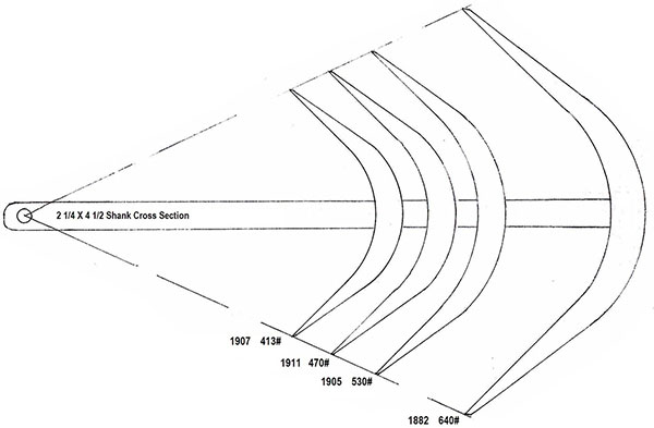
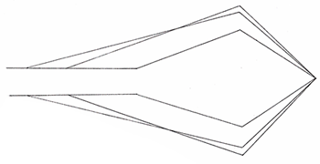
This sketch traces the changes in shank length of one size anchor, as defined by its shank cross section and demonstrates how standard geometry then altered the anchors size and weight.
- In 1882 this anchor, with a 2 ¼ x 4 ½ (2:1) shank cross section, had a shank length of 99 inches. and a weight of 640#.
- In 1905 the shank was shortened to 80in. and weighed 530#.
- In 1907 the shank was reduced further to 60in. and weighed413#.
- In 1911 the shank length was increased to 68½in. and the increased to weight 470#.
This illustrates the continuous effort to stiffen the shank and decrease its loading i.e. holding power by decreasing the shank length. This process had a profound effect on the largest anchors and only a small effect on those anchors below 50#.
Testing
- Proof test values for all anchors first appeared in 1907 and were modified in 1911.
- Each anchor was proof tested following assembly; a Lloyds Certificate of test was available for an additional fee.
- In April 1914 NGH tested three steel fluke castings for KATOURA’s (#725) 1260# anchors. Two of the castings failed due to casting flaws and large grain structure. This is the earliest documentation of a cast steel anchor fluke I have located. If these were some of the first cast steel flukes the flaws and grain structure. The problems noted might indicate they were early on the learning curve of how to best cast and heat treat these specific castings. The shank used for this test was wrought iron as no pattern was ever made to cast this size shank. The test note states that as a result the shank was bent indicating the wrought iron had been stressed beyond its yield strength. (Additional anchor test records may exist in some technical file or notebook)
- Test failures of several fluke castings produced by the Millbury Steel Foundry in 1925 and 1926 are noted on casting cards and resulted in withdrawing all work from Millbury by the fall of 1926.
A Photograph of the HMCo. anchor proof testing machine appears on page 12 of “Yachts by Herreshoff.” The photograph shows a completely assembled folding stock anchor undergoing test.
Bill Angle
The bill angle of the cast flukes increased as the anchor size increased. The smallest bill angle I can document is 79 deg. on the 7½ # anchor and the largest is 112 deg. on the 542# anchor. (I still need to determine the maximum bill angle and the criteria used to determine the bill angle. The data available demonstrates it is weight related). Increasing the bill angle increased the area of the palm where it is most important, at the maximum penetration of the fluke where the bottom soil is most dense. The greater weight of the larger anchors enabled a less sharp bill to penetrate the bottom soil equally as well as the sharper point of a lighter anchor. The following data has been assembled from measurements of existing anchors and information derived from drawings.
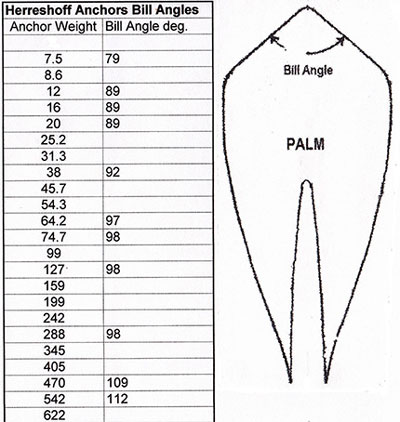
The tabular anchor drawings issued in 1882, 1905, 1907,& 1911 make no reference to, or provide a value for, the bill angle. The eight drawings describing the cast anchors provide the only definitive information I have been able to locate regarding bill angles, this may indicate the concept of a varying bill angle was also introduced with the transition to cast steel flukes.
Materials of construction
Wrought iron was the material of construction specified on all drawings from 1882 until shortly after 1911. In the 1800’s wrought iron was the structural metal of the day, it was strong, ductile, corrosion resistant and easily worked by blacksmiths. The stock and shank of these anchors are reasonably simple to forge; however, to accurately manufacture the large wrought iron flukes required highly skilled blacksmiths. The HMCo. had a large and very capable blacksmith shop that forged these anchors as well as the considerable iron work required by the large HMCo. yachts. By 1914 the material for the flukes and shanks was in the process of changing from wrought iron to cast steel, a 1916 drawing specified medium carbon steel for anchor stocks. (I have not been able to determine exactly when carbon steel was first introduced for anchor stocks but it is likely to have been at the same time the shanks and flukes became steel castings.) For design purposes involving tensile and yield properties rolled, cast and welded steel may be interchanged with confidence*.
*Mark’s Mechanical Engineering Hand Book
At the same time cast manganese bronze was specified for the shanks and flukes for those anchors 12# and smaller with stocks made from Tobin bronze rod.
As the table below indicates cast steel is a significantly stronger material than wrought iron.
| Tensile Strength | Yield Strength |
|---|---|
| Wrought Iron — 48,000psi | 30,000 psi — specified for stock, shank, flukes prior to cast steel. |
| Cast Steel — 70,000psi | 40,000 psi — specified for cast flukes and shanks 1916 |
| Med. Carbon steel — 85,000psi | 54,000 psi — specified for stocks on 1916 drawing 74-61 |
| Manganese Bronze — 90,000psi | 45,000 psi — specified for the 7.5# and 12# anchors drawing (CDA 862) |
| Tobin Bronze — 79,600psi | 54,300 psi — specified for stocks of the cast bronze anchors (Alloy 4641) |
Adoption of the Herreshoff Innovations by others
Many anchor manufactures adopted the concept of the extended palm to increase holding power and reduce the probability of fouling the anchor rode. The most common design was a diamond shaped palm with the bill angles held constant throughout the manufactures range of anchor weights. Bill angles varied from one manufacturer to another with 90 deg. being the most common.
The above sketch is a representation of the most common diamond palm shapes taken from existing anchors.
Only a few adopted the three-piece design
Henry B. Nevins Inc.
Nevins designed a family of geometrically similar three-piece, cast steel folding stock anchors for use on many of the yachts they built. These anchors were well made but of a different geometry than the HMCo. anchors. The socket connection joining the shank and flukes was tapered, the shank was oval in cross section and therefore would also present less resistance to the bottom soil than an equivalent weight round cross section. Based upon measurements the Nevins anchors appear to be very efficient but have slightly less palm area than the comparable HMCo. anchor. Some Nevins anchors were also cast of manganese bronze.
Consolidated Shipbuilding
Consolidated Shipbuilding designed a family of three-piece cast steel anchors; the geometry also differed from the HMCo. anchors. The Consolidated anchors incorporated a single tapered socket to connect the shank and flukes and the bill angles were smaller than comparable HMCo. anchors. Unlike the HMCo. anchors the bill angles of the Consolidated anchors tended to decrease slightly as the anchors increased in size. The Consolidated shank design was less stiff than the equivalent HMCo. anchor. The material specified was open hearth steel, the drawings, all dated 1930, did not specify if these anchors were to cast or forged. Based upon the dimensioning on the drawings and the material specified my judgment is anchors were intended to be cast.
George Lawley & Son
Lawley also developed a Herreshoff style three-piece anchor design for use on their yachts. A drawing dated September 4, 1917 from the Lawley Collection at the MIT Museum describes four Lawley anchors of 65#, 85#, 110# and 200#. The drawing is well dimensioned but contains no materials of construction or pattern numbers. The anchors on this drawing do not share a common geometry and the crown socket joining the shank and flukes was straight rather than tapered. The bill angles vary from anchor to anchor but the change was not directly related to anchor size. The bill angles were smaller and the area of the palm was slightly less than the equivalent weight HMCo. anchor. The shanks of the Lawley anchors were significantly less stiff than comparable weight HMCo. anchors.
Merriman Brothers
Information from Merriman Brothers catalogs:
- 1928 catalog illustrated a three-piece anchor and stated “These anchors are designed in accordance with the ideas and experience of the leading naval architects”. The anchors were described as available in both two and three-piece styles from 40#-300#.
- 1933 catalog advertised Herreshoff type anchors with hand forged shank and stock and cast steel head (flukes). The stock of the folding stock anchor illustrated in the catalog had no taper and a ball only on the bent end of the stock. Both folding and straight stock anchors were available in thirteen sizes from 65# - 400#.
- 1948 catalog advertised Merriman made Herreshoff straight stock and folding stock anchors and stated “the anchors are made using original Herreshoff patterns employing identical hand forgings, testing methods and materials.” Only fourteen anchor sizes, 30#-400# were listed as available. The folding stock anchor illustrated had no taper and a ball on only the bent end of the stock.
- 1957 catalog advertised Merriman made Herreshoff straight stock and folding stock anchors and stated “the anchors are made using original Herreshoff patterns employing identical hand forgings, testing methods and materials.”, however only six anchor sizes, 30#- 260# were listed as available.
- 1962 catalog illustrates a straight stock anchor with the special shackle and the same text as the 1957 catalog, however, only six straight stock anchors 65#-400# were listed as available.
The 1948 Merriman catalog accurately implies that Merriman had acquired the rights to the Herreshoff patterns following shutdown of the Herreshoff Manufacturing Company in 1945.
One casting card entry, for flukes of the 38# anchor, indicates that on August 28, 1929 two castings were ordered for “Merriman Stk” (stock). Another card indicates that on July 12, 1926 two fluke castings were ordered for Luders. In view of the very small number of surviving casting cards for anchor castings it is reasonable to expect there were other anchor parts cast for Merriman and perhaps others. Each of the surviving anchor casting cards has one or two entries for stock. Although the HMCo. did not advertise anchors until the 1930’s an inventory card for July1903 records (87) straight stock anchors from 10#-460# in stock and on June 1905, an inventory of (59) straight stock anchors. A smaller number of folding stock anchors were listed on the same inventory record.
Burgess Swasey and Paine
The Dan Gregory Ships Plans Collection at Mystic Seaport contains a very detailed 1923 Burgess Swasey and Paine drawing (MSM accession number 11:19) describing (6) folding stock anchors which are exact dimensional copies of the corresponding 1911 HMCo. folding stock anchors. The drawing contains no pattern numbers and no indication of who was to manufacture the anchors. Cast steel is specified for the flukes and wrought iron for the shanks and stocks. The stock shown on the drawing is the older style tapered stock with balls on each end. There are no dimensions provided for the tapered socket connections at the crown, it may be the blacksmiths who forged the shank were expected to match the tapers as determined by the fluke casting. This might also indicate Burgess Swasey Paine intended to purchase the fluke castings from HMCo. The wrought iron specification is interesting as 1923 is long after HMCo. shifted to steel castings for many shanks and the simplified stock design made of steel.
Since both L. Francis Herreshoff and A. Loring Swasey, who had been employed as chief designer at the HMCo. from 1917-1923, were both part of Burgess Swasey and Paine it doesn’t take much to figure out how this drawing was created.
List of HMCO. drawings describing the straight and folding stock anchors in the haffenreffer—herreshoff collection at the MIT Museum.
| Drawing | Date | Title |
|---|---|---|
| 74-01 | March 29,1882 | Fabricated Sizes of Anchors |
| 74-44 | June 12, 1905 | List of Straight Stock Anchors |
| 74-45 | June 16, 2012 | List of Folding Stock Anchors |
| 74-51 | May 8, 1907 | Straight Stock Anchor List |
| 74-52 | May 11, 1907 | Folding Stock Anchor List |
| 74-54 | January 12, 1911 | Folding Stock Anchor List |
| 74-54 | January 14, 1911 | Straight Stock Anchor List |
| 74-60 | March 30, 1915 | Anchor for # 744 Class ( 7.5# ) |
| 74-61 | January 29, 1916 | 127 & 64 lbs. Cast Steel Anchors |
| 74-62 | March 4, 1916 | 12 and 16 lbs. Anchors |
| 74-64 | May 26, 1916 | 288 and 199 LB Cast Steel Anchors |
| 74-69 | December 18, 1918 | 20 LB Anchor |
| 74-70 | January 4, 1919 | 64.2 & 74.7 LB Anchors |
| 74-71 | July 1, 1919 | 405 LB Anchor |
| 74-72 | December 24, 1918 | 31.3 & 45.7 LB Anchors |
| 74-72 | No Date on drawing | 542 LB Anchor |
| 74-81 | March 8, 1927 | 470 LB Cast Steel Anchor |
All illustrations within this document were drawn by the author, and are based upon the author’s research and analysis of the original Herreshoff Manufacturing Company drawings in the Herreshoff-Haffenreffer Collection at the MIT Museum.
In addition to the drawings available in the Herreshoff-Haffenreffer Collection at the MIT Museum, there are examples of Herreshoff and Merriman three-piece anchors at the Herreshoff Marine Museum and Mystic Seaport Museum. The Mystic Seaport collection also contains a Nevins three-piece anchor. The curators of all these museums were very helpful providing access to and information about their collections which was critical to the development of this document.
Current Manufacturers of Three-Piece Stock Anchors
- JM Reineck & Son — Reineck produces reproductions of 7 ½# and 17# Herreshoff folding stock anchors, cast from manganese bronze.
- P.E. Luke — Luke produces a series of (9) galvanized steel three-piece straight stock anchors weighing 25#- 200#.
- Kingston Anchors — Kingston advertises a series of (7) galvanized steel three-piece Herreshoff style straight stock anchors weighing 15#-199#.
- Historical Arts and Casting — Historical Arts and Casting has tooling for 40# and 20# bronze reproductions of Herreshoff folding stock anchors.
J.L. Giblin, January 8, 2013
The History of the Design and Development of an Engineered Product
